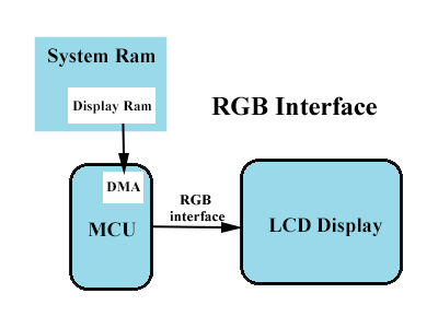
Explains the RGB interface of the parallel transmission method of TFT LCD and how to generate row and column drive signals from the RGB interface of the digital parallel transmission method.
Parallel transmission RGB interface
Let’s start with the basic concept of parallel transmission of RGB data, that is, each base color signal data is transmitted using a separate data line, corresponding to an 8-bit LCD panel, R, G, and B sub-pixels are represented by 8 bits of data, then RGB data, a total of 24 bits, and RGB data lines are also a total of 24. As an analogy, the data is transmitted in parallel by lining up each primary color data in a horizontal line and outputting it together.
TFT panel working principle
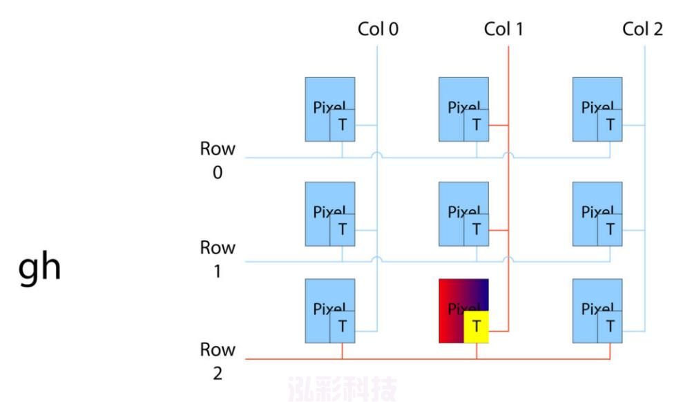
We have to understand the working principle of TFT LCD panel first. The LCD panel is composed of a series of liquid crystal sheets. The crystals themselves do not emit light. When there is no electric field, the crystals are organized in a random pattern. When an electric field is applied, the crystals are aligned with the electric field. The electric field of various intensities acts as a “gate” that allows backlights of different intensities to pass through the crystal. When the crystals are aligned perpendicular to the backlight, the backlight cannot pass through the crystal. From the point of view of electronic structure, the LCD panel consists of a grid of electrical signals. Pixels are processed by a matrix in which each interaction belongs to a pixel. Each pixel is connected vertically to rows and columns by a transistor. When the rows and columns are selected by the IC controller, the pixels in the row and column interaction are enabled or disabled.
A pixel generates a specific color
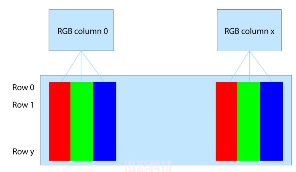
In order for a pixel to generate a specific color, 1 pixel consists of 3 segments, which are passed through red, green and blue filters to form an RGB pixel. For a 320240 RGB TFT display, there are actually 960 (3203) columns and 240 rows.
The RGB interface is responsible for sending image data information (gray levels and colors) in real time. The image data is transmitted digitally as “0” or “1” via TTL voltage levels. For the RGB interface, there is a corresponding line for each signal. Below are the signal connections for the RGB interface at 24bits per pixel.
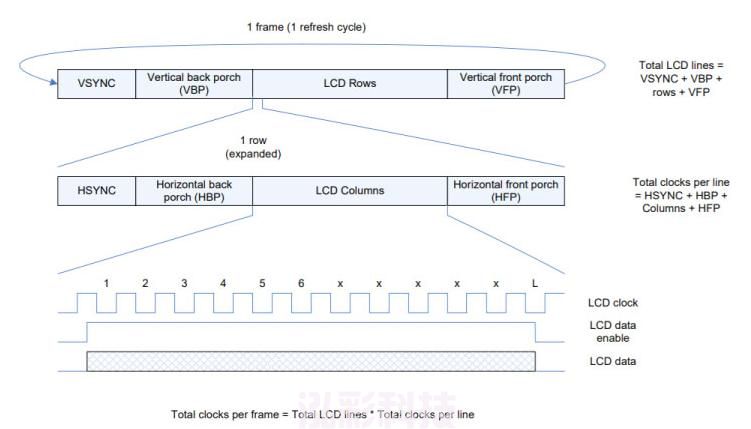
Vertical Sync VSYNC sets the start of a new frame. No image data is available during the VSYNC synchronization pulse, which is marked with VBP and VFP. the same principle applies to the HSYNC synchronization pulse, marked with HBP and HFP. the HSYNC pulse is responsible for a new line. Between the two HSYNC pulses, one row (line) of gray-level RGB color data must be transmitted. Since a TFT display can drive 3 segments (1 pixel) per clock, the length of the LCD CLK is determined by the number of columns of the resolution. For example, for an LCD display with a resolution of 480*272, we assume the following parameters.
The above is a brief introduction to the RGB interface for parallel transmission.Shenzhen Hongcai Technology Co.,Ltd. is a professional manufacturer of small and medium size, 2.4 inch LCD display, 2.8 inch display, LCD display, mainly producing SPI serial LCD display, widely used in different high-tech industries, the factory also supports industry customization, re-change PIN definition, stable resources, solid quality, cheap and affordable price. Solid quality, cheap and affordable price, welcome customers with demand directly click online consultation.


